My own Solar Power Plant – part II
Published on
Tags: solar, electrical, DIY
In my first post, I've explained in brief about a 100W solar power plant that I set up at my home. In this post, I'll get a lot more technical in order to explain the issues faced by me after setting up the power plant. (This post is for electrical and electronics students). Here is the solar panel setup for your reference. And here is the raw dump of the log which I did while doing the experiment.
#1 Resistance in the wires to inverter:
On the first day, I connected my laptop to the inverter. The battery lasted from 6:50PM to 10:40PM after which the inverter gave a low battery beep and shutdown. I checked the battery voltage and it was high at 11.72V. I thought that the inverter was behaving funny and needed to be checked. The next day, I charged the battery with the solar panels to full(or I thought so) and connected to the load in the night. I finally discovered the problem today. I was using fairly long wires to connect from the battery to the inverter(5m approx) and there was a considerably voltage drop on the wires about 1V! When the battery had 12.38V across it, the inverter had only 11.51 V across it! Measured the voltage at the battery as well as a joint I made with the wires from the battery and a wire from the inverter. Just look at the differences below!
| Time | Battery Voltage | Battery voltage at joint | Load type |
|---|---|---|---|
| 18:59 | 12.38V | 11.51V | Laptop document edit+BB modem Download |
| 19:20 | 12.32V | 11.44V | Laptop browsing + BB modem DL |
| 19:47 | 12.22V | 11.36V | Laptop browsing + BB modem DL |
| 20:14 | 12.14V | 11.30V | Laptop browsing+ BB modem DL |
| 20:49 | 12.01V | 11.12V | Laptop document edit + BB modem DL |
| 21:20 | 11.86V | 11.10V | Laptop most at rest + BB modem DL |
| 21:42 | 11.82V | 10.99V | Laptop mostly idle + BB modem DL |
| 21:53 | 11.78V | 10.64V | Laptop mostly idle + BB modem DL |
| 22:11 | 11.71V | 10.66V(!) | Laptop browsing + BB modem DL |
| 22:30 | 11.62V | 10.50V | Laptop video + BB modem DL |
| 22:40 | 11.57V | 10.46V | Laptop video + BB modem DL |
| 22:46 | 11.54V | 10.44V | Laptop video + BB modem DL |
| 23:00 | 11.46 | 10.35V | Laptop video + BB modem DL |
Inverter shutdown as it detected a voltage of < 10.4V
If the load were heavier, naturally there will be more voltage drop across the reistance of the wires (V=IR!).
After this, I brought the inverter closer to the battery and shortened the connection drastically. The inverter was able to operate for some more time.
#2 Inverter self Load
I connected an ammeter (unfortunately an AC one which gave inaccurate results for DC) in the battery-inverter wires and found that the inverter consumes about 1A of battery current even while no load is connected. The laptop consumes another 2A and the total load is about 3A. Hence with laptop, 33% of the power(12W) is going to keep the inverter in operation.
#3 Resistance of the wires connecting solar panel.
In the third day I faced a similar problem with the wires connecting the solar panels to the battery. I hadn't discovered this previously, as I did not have an ammeter then. The solar panels were supposed to give a current output of greater than 5A in full sunshine, but it was giving only 2A. On measuring the voltage generated at the solar panels(18.5V) to the voltage near the charge controller (12.5V). I found a 6V difference while supplying 2A of current! Of course the wires were also bad – it was a single strand wire with the thickness of a pin, resulting in higher resistance. When 2 A of current was supplied by the solar panels, the voltage drop across the wires connecting the solar panels and the charge controller was 6V, meaning a resistance of 3ohms. The battery voltage was 12.5V volts. In order to supply more current, the solar panels has to increase their voltage,which is not possible without decrease in current. I then replaced the wires at 4PM and the current supplied by the solar panels considerably improved to 3A ☻
| Time | Charging current | Battery voltage |
|---|---|---|
| 08:05 | 1.12A | 12.25V |
| 08:52 | 1.95A | 12.40V |
| 09:20 | 2.09A | 12.45V |
| 11:00 | 2.18A | 12.66V |
| 15:00 | 2.10A | 13.01 |
| 16:30 | 2.96A | 13.23V |
| 17:00 | 1A | – |
At 5:00PM, the solar panels came under a huge shade and it resulted in a drastic drop of output to 1A.
#4 Battery sluggishness:
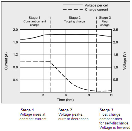
Without knowing much about lead acid battery, I assumed that if I buy a 35Ah lead acid batery then with solar panels supplying 5A of current, I can charge in 7 hours. But I was wrong. The lead acid battery doesn't like being force fed lot of food in a short amount of time. I went through the site www.batteryuniversity.com and found a lot about the battery which I previously never thought of. It seems that the lead acid battery charges in two stages:
Firstly (like a hungry person) constant current mode during which it takes in lot of currrent and charges upto 70% of the battery capacity. The rate of charge given by many manufactures is 0.15C where C is the Ampere hour capacity of the battery(so for my battery the safe limit is about 4.5A). This stage lasts for about 5-8 hours. The end of this stage reaches at 13.2-13.6V depanding upon the rate of charging and the battery voltage shoots up and has to be regulated by the charge controller to a safe voltage, typically 14.4V. This results in the constant voltage phase.
In the second stage, (like a person who finishes his meal) the battery operates in constant voltage mode where in the battery voltage is maintained at a safe limit(14.4V typical) by the charge controller/ regulator. The battery draws a smaller current that exponentially decreases from the value of constant current stage to zero. When the current drawn reaches 3% of the value, the battery is considered as fully charged. This stage is called "topping charge" and it takes about 60% of the time for completing 30% of the charge! This is important for the life of the battery else the battery will stop accepting full charge.
Thirdly, after being fully charged, the battery should be kept at "float voltage". This is to compensate for the high self discharge of the battery which is 3-20% per month.
If one looks at the second stage called constant voltage stage, the solar panel output is not being used fully resulting in wastage. You cannot skip the stage either, because it will result in reduction of the battery life. I'm currenly doing a project to handle this problem: I want to design a charge controller that will charge two batteries: one battery with low state of charge at constant current stage and another battery at high state of charge in constant voltage phase. This makes sure that the solar panel output is utilized fully.
Any comments on this welcome!
